By Caleb, February 4, 2026
Why engineering matters for sleepers and seats in high-roof passenger vans


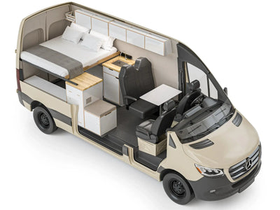
When you convert a high roof van for sleeping or add or remount captain chairs, you change how loads flow through the car structure during normal use and in extreme events (NHTSA crashworthiness guidance). This piece looks at the engineering (NHTSA vehicle safety standards) and physics behind safe seat and sleeper installs in high roof vans. It highlights force paths, mounting strategies, and failure modes. Practical conversions balance comfort and usable space with strong structural design so owners and shops trade short-term convenience for long-term durability and occupant protection.
Safety risks from improper seat and sleeper installations
Wrong anchor points, small fasteners, or changes to seating shape can produce focused stresses, unwanted twisting forces, and undesired motion for occupants. Common failure modes include bolt shear, sheet-metal tear-out, bearing failure in thin-floor conditions, and unintended load transfer into non-structural panels.
- Respect factory anchor points. Whenever possible, use OEM seat and belt mounting locations or reinforced zones designed by the manufacturer. Avoid drilling into thin sheet metal or cosmetic panels that were never meant to carry crash loads. For Sprinter platforms, the Mercedes-Benz Sprinter body structure and safety design is engineered with specific load paths and anchor zones in mind.
- Trace the full load path. For every seat, belt, or sleeper, follow the force path from the occupant, through the hardware and structure, into the van’s frame or cross-members. Every link in that chain must be strong enough for crash-level loads.
- Use proper backing plates. When you can’t mount directly to a frame member, use thick, wide backing plates to spread loads across a larger area of floor or cross-member, reducing the risk of tear-out or local crushing.
- Size and grade hardware correctly. Choose bolts with the right diameter, strength class, and grip length for the joint. Undersized or soft hardware is a common failure point in high-roof passenger van safety issues.
- Control motion, not just strength. Seat geometry, belt routing, and sleeper height all change how people move in a crash. Keep lap belts low on the pelvis, shoulder belts on the chest, and avoid layouts that let occupants submarine or twist. The NHTSA’s seat belt guidance emphasizes proper belt positioning to reduce injury risk.
- Protect against fatigue and loosening. Use locking nuts, thread-lockers, and proper torque so hardware doesn’t back off over time. Inspect high-load joints periodically for cracks, elongation, or fretting around bolt holes.
- Don’t bury structure under cabinetry. When adding sleepers or storage, keep access to key structural members and mounting points. Avoid designs that block or weaken those areas just to gain a little extra storage volume.
- Check regulations and test data. Review NHTSA guidance, OEM upfitter manuals, and any available crash-test information (NHTSA crash-test database) before finalizing your layout. Legal seating and belt installs are the foundation of high-roof passenger van safety.
Sleepers built over or next to taken-out mounting points can change how load travels into the frame and floor cross-members. Think like an engineer: trace the path of motion forces from the person into the van structure and check each connection in that chain.
Core engineering concepts for seat and sleeper installations
Load paths and force distribution
Seats transmit rider forces into the van through mounts and backing plates. In a straight-line slowdown event, peak loads focus at belt mounts and seat base mounts, and federal crash testing reflects these high restraint loads (NHTSA crash test ratings).
Design the joint so loads flow into frame members or into backing plates that spread forces over a wide area of floor or cross-member. Avoid setups that put focused load on thin sheet metal alone.
Modes of failure to design against
Common hardware failure modes include bolt shear, thread strip, bearing failure of thin material, and pull-through of bolts. Secondary modes include bolt loosening under cyclic loads and fatigue cracking in backing plates or nearby structure. Address these by selecting the right bolt class, grip length, backing plates, and using thread-locking or prevailing-torque nuts where practical.
Seat geometry and occupant kinematics
Seat location, pitch, and belt routing change rider motion under load. Changing seat pitch or moving the seat forward or back can change the lap-to-shoulder belt shape and the moment about the pelvis. When you move seating spots for comfort or sleeper layouts, confirm that belt anchor locations keep a stable lap belt path and shoulder engagement. Keep loads on the pelvis and shoulder, not the abdomen.
Hardware, materials, and fastening best practices

Anchorage types and reinforcement strategy
Anchor into frame members whenever you can, whether you’re working on a Mercedes Sprinter box truck or a Mercedes Sprinter cargo van. Where that is not practical, use properly engineered Sprinter van seat mounting brackets or a Mercedes Sprinter seat mounting kit with backing plates sized to spread loads into nearby structure, just as you would in a careful Sprinter box van conversion. OEM upfitter documentation, such as the Mercedes-Benz Sprinter upfitting guidelines, is a useful reference for identifying structural zones and recommended attachment strategies.
Backing plates should be thick enough to avoid local bearing failure and sized to spread load so that bearing stress in the sheet metal stays well below its yield strength. Through-bolts with backing plates into frame members are a solid approach for high-load points.
Fastener selection and torque discipline
Choose bolts with enough shear and tensile strength. Use SAE Grade 8 bolts or similar high-strength hardware where high loads are expected. Avoid single-bolt setups that focus load; prefer multi-bolt patterns that spread load and provide backup.
Record and follow torque values that fit the bolt class and joint materials. Common practice examples: a 1/2-inch Grade 8 bolt into a backing plate will have far higher shear strength and clamp load. This is much stronger than a 3/8-inch hardware-only setup bolted into thin sheet metal.
Backing plates, welds, and through-bolting
Backing plates increase bearing area and reduce local stress. When you can, place backing plates over frame ribs or cross-members and use through-bolts that clamp into those plates. In setups that allow welding, welds must be sized and laid out to carry the same load paths as bolted joints; think about fatigue and how easy it is to inspect when choosing welding over bolting.
Design checks and simple calculations
Estimating design loads
Start with a safe rider weight and a peak slowdown factor to estimate mount loads. For example, using a 200-lb rider and a safe 20g peak pulse gives a peak force of 4,000 lbf directed through the restraint system.
Use safety factors and spread-out load patterns to size bolts and backing plates. Engineers often apply extra factors for unknowns in pulse shape and joint stiffness.
Shear and bearing checks
Perform a shear check on possible bolt sizes using standard allowed shear strength for the bolt material. Also perform a bearing check on the plate it connects to using bearing allowed stress for the sheet or backing material. If the bearing stress gets close to the yield of the sheet material, increase plate thickness or bearing area to reduce local strain and prevent pull-through.
Fatigue and cyclic loading
Vans see many miles and many load cycles, so think about fatigue when laying out seat mounts and rails. Avoid tight-radius shape changes where cracks can start, and use fillets or rounded cutouts on backing plates to lower stress hot spots. If a removable rail is used, ensure locking mechanisms resist small motion that can speed up bolt loosening or fretting fatigue.
Practical rules for captain chairs and sleeper modules
Distinguishing permanently mounted seats from removable rail-mounted chairs
Fixed seats are best bolted through into frame members or into properly strengthened floors. Removable or rail-mounted chairs can be okay if the rail system and locking mechanism are rated for uplift, shear, and rotation loads. Rail anchors must also transfer loads into structure or strong backing plates. Choose high-quality rails with positive mechanical locks and clear engagement indications.
Preserving belt geometry and restraint effectiveness
Retain or re-create belt anchor layout that keeps lap belts low on the pelvis and shoulder belts across the collarbone. Moving seats without fixing belt anchor points can produce poor load paths and increase risk of harmful rider movement. Where built-in belt systems are removed or relocated, match the original anchor stance and load direction as closely as possible.
Airbag and occupant sensing considerations from an engineering perspective
Seat motion and rider posture affect how restraint systems work with extra restraint devices. While not a rules discussion, the real engineering point is simple: avoid seat placements or offsets that move riders outside expected sensor envelopes. Do not change initial rider-to-airbag distances enough to alter deployment timing or cushion interaction. Modern vans integrate advanced airbag and sensor systems, and resources like IIHS crash test evaluations highlight how occupant position affects real-world outcomes.
Conversion best-practice checklist for engineers and shops
Checklist
1) Map load paths from rider and belt anchor to the nearest frame member; avoid relying on thin sheet metal alone. 2) Select bolts with enough shear and tensile strength (use stronger classes where needed) and define torque values. 3) Use backing plates or bolts that pass through structure to spread loads and prevent pull-through.
4) Keep belt routing layout in line with good lap and shoulder restraint. 5) Detail rail locks and removable joints to resist uplift, shear, and rotation. 6) Think about fatigue and design for many load cycles; avoid stress hot spots. 7) Retain photographic records of critical attachment details and a simple technical note describing load assumptions and chosen hardware for future reference.
If you’re planning seat or sleeper changes and want them designed and put in safely, contact us to talk through your high-roof passenger van safety needs or explore our professional van conversion services for Sprinter box and cargo platforms. Whether you need a full Sprinter van seating layout, a single-row bench install, or a custom Sprinter passenger seat mounting solution for your camper build, an engineered approach keeps your rig safe.
Common myths, pitfalls, and how to avoid them
Myth: Fit equals adequate load path
A seat that fits in space does not guarantee good load spread. If the mount relies on thin sheet metal or single-point bolts without backing, the setup is likely too small for peak inertial loads. Use multi-point anchorage and backing plates to reduce local stress.
Pitfall: concentrating loads in non-structural panels
Pitfall examples include mounting rails to floor panels that are not backed by cross-members or relying on trim panel spots for final load transfer. Always find or create a path to structure for main restraint loads; when in doubt, add backing plates that tie into frame ribs or cross-members.
Practical shop tips
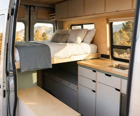
Label and record part numbers and torque values at install, use thread-lock methods where needed, and check key bolts after first road use to ensure clamp loads remain stable. When laying out removable setups, favor mechanical positive locks that provide feel and visual feedback when engaged. If you want to see how these principles show up in finished rigs, browse our camper van build gallery for real-world examples of safe seating and sleeper layouts, including different Sprinter van seat mounting configurations.
FAQ
Are van captain chairs acceptable from an engineering standpoint?
Yes, when their mounting system gives a clear, well-spread load path into frame members or strong backing plates and the rail locks resist uplift, shear, and rotation. Use correctly sized bolts and backing plates and check belt layout for good restraint. For families planning to use captain chairs alongside bunks or convertible beds, our family camper van layouts show how to combine safe seating with practical sleeping zones.
Can I remove factory seats to make a sleeper area without compromising structure?
Yes, if you plan the new mounts so that original load-bearing points are replaced by equal or better load paths. That usually means strengthening the floor or installing backing plates and through-bolts into frame members where needed to restore or improve load spread. If you’d rather start from a professionally engineered platform, consider one of our turnkey camper vans where seat and sleeper structures are already designed to handle crash-level loads and integrate with safe Sprinter van seat mounting practices.
When is through-bolting preferable to sheet-metal fasteners?
Through-bolting with backing plates is better when expected loads are high or when the sheet thickness on hand cannot carry bearing stresses without local yielding. Through-bolts provide higher clamp load, more bearing area, and backup compared to single bolts into sheet metal. DIY builders who want to pair robust mounting with a complete interior package can look at our DIY van conversion kits, which are designed to integrate with safe anchorage strategies and flexible Sprinter seating layouts.